Switchastrophes: When Manufacturing Goes Bad

Figure 1: Oh yeah, this is going to be an interesting one...
There have likely been millions upon millions of MX-style mechanical keyboard switches produced around the world in just the last handful of years alone. Screw going back to the 1980’s when Cherry first debuted the MX switch design – the combined production output over most of our lifespans in the hobby is almost impossible for any of us to fathom. And yet, for all of those switches produced and all of those switches we’ve encountered over the years, have any of you ever actually encountered a truly defective switch before? Seriously think about that question for a minute. I’ve bought bad bags of produce from the store, broken blenders, and fucked up cars all without even realizing it and yet I’ve never organically encountered a switch in my collection that was non-operational. In fact, I’ve had to go out of my way just to try and source defective switches with unique production errors just to see what they look like and it was far from an easy task. So if you could answer that question for the affirmative and you’ve come across a defective switch or two in your time, then consider yourself incredibly lucky for what you’ve witnessed.
The vast majority of people don’t even recognize just how good the manufacturing and quality control of switch production facilities are. Everyone from the largest, most well-known manufacturers down to the no-name pop ups cranking out blue colored clicky OEM switches basically never let production mistakes escape their factory. While switches may not seem all that complex to just an average mechanical keyboard enthusiast, they are actually pretty impressive feats of engineering all things considered. What’s even more impressive is how these components are manufactured and come together so seamlessly day in and out at factories all over the world. However, I realize that most people have no idea of how switches are made at all and this is likely why many people hardly think about their journey to their door and just how remarkable it is that basically all switches make it out from the factory in perfect shape. In order to perhaps instill a little bit more awareness of and awe in the manufacturing process of switches, this short article walks through the manufacturing process with lots of pictures and a bit less words than my normal week in and out writing – but with a twist. Rather than just showing each step of the process, I’ll also be including photos of factory production errors that I’ve been lucky to accumulate over the years and show you just how wrong production can go at each of these stages. After all, while switchastrophes are rare, they are incredibly interesting looks into the production process.
Step 1: Injection Molding

Figure 2: Injection molding production diagram from Wikipedia.
As you may have been able to put together based on my rampant discussion of switch ‘molds’ and the details contained within them in my full-length switch reviews piled up somewhere else on this website, all plastic components of switches first start at the injection molding process. In order to do this, manufacturers will first machine large blocks of metal with a series of designs and channels interconnecting them known as the ‘molds’ of a switch component. The bottom housings, top housings, and stems each have two different halves of molds which are pressed together during the production process to form one large, interconnected network of channels that start out at the point where hot, molten plastic is injected into the molds. Once injected into the pair of molds, the plastic will flow through all of the runners and channels as shown in Figure 2 above and fill out up to a couple dozen identical copies of the component being made. After some time for the parts to cool and solidify, the molds are cracked open with the stems or housings, as well as their connected runners, being dumped out and collected for some inspection and cleaning up procedures. While some factories will do quality control checks here, its also after this step that individuals may physically separate the pieces from their injection sprues and runners not unlike how Gundam model parts arrive if you’re degenerate enough to understand that reference.

Figure 3: Photo of switch component molds from Lume Keebs’ visit to Gateron. (Video linked at bottom of article)

Figure 4: Tactile brown switch stems fresh out of the injection molds still connected to their runners.
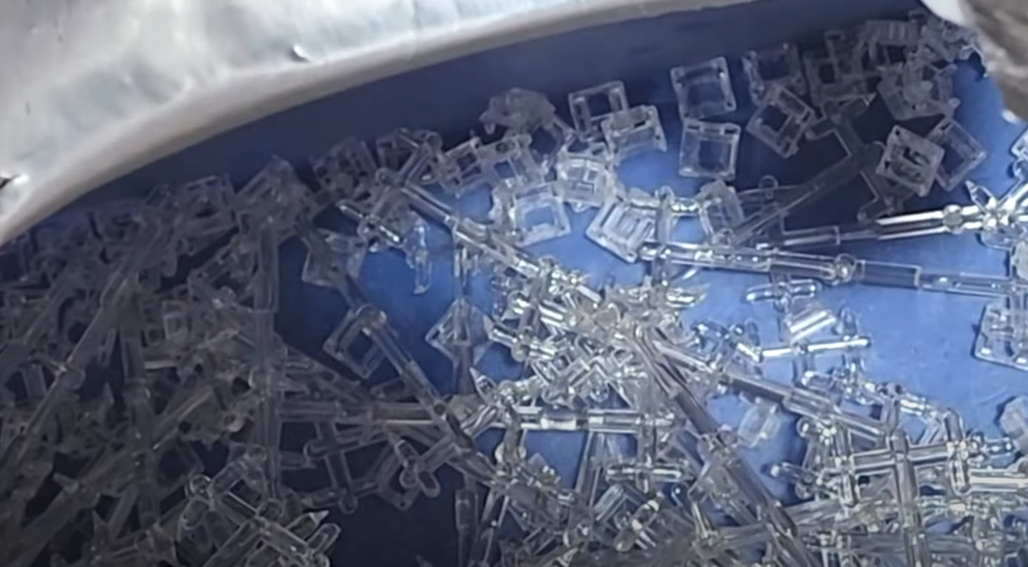
Figure 5: Clear top housings being separated and sorted from their injection molding runners.
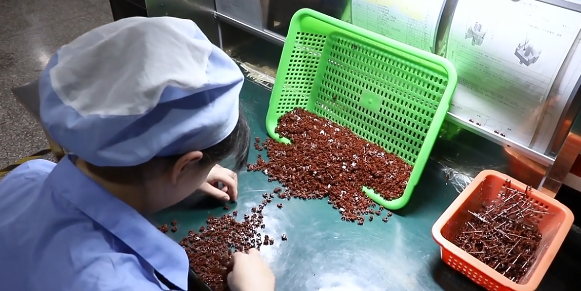
Figure 6: Tactile brown switch stems being inspected and separated from their runners in a manual quality control process.
However, not all switch parts get cleanly injected as a result of manufacturing issues. While extremely rare, defects in stems and housings can look something like this:

Figure 7: Failed injection molds of two different stems and a bottom housing.
Step 2: Leaf Cutting and Insertion
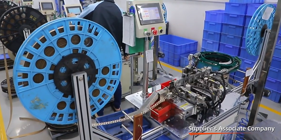
Figure 8: Large overview image of how metal switch leaves are brought into the factory, stamped out, and sent to a sorting machine.
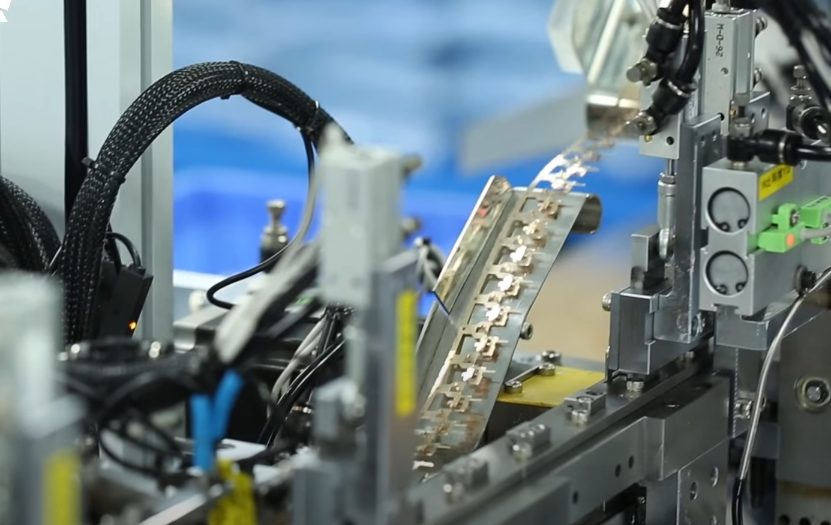
Figure 9: Closer view of the larger metal switch leaves being fed out from their spool towards the stamping machine.
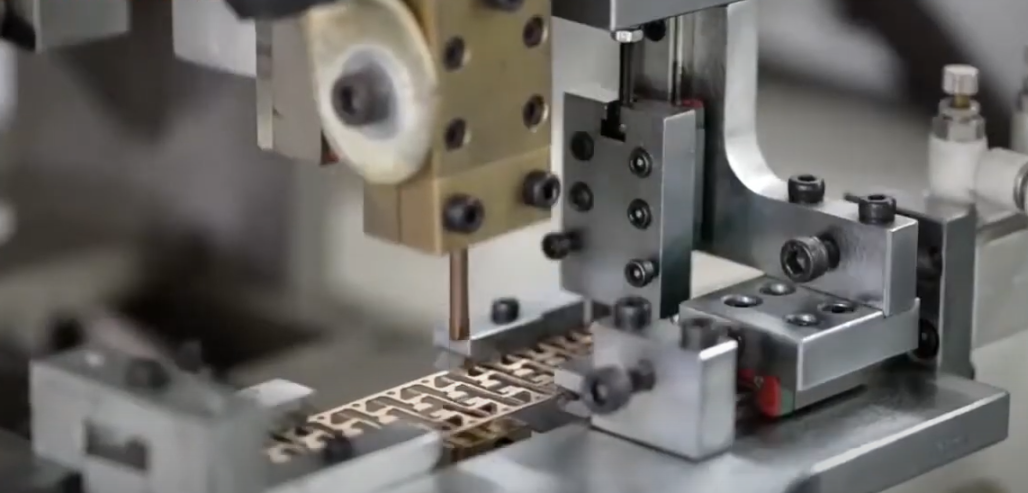
Figure 10: Closer view of the smaller metal switch leaves being fed out of their spool towards the stamping machine.
Both the larger and smaller leaves of MX-style switches arrive to factories partially cut out of long, thin strips of metal that are wound around giant spools. As can be seen in the photos above, the spools are then hooked into machines which slowly roll out the leaves, stamp them out of the metal strip, and then shuttle them elsewhere for the next steps of switch assembly. After the bottom housings have been made and are staged up on another end of the machine, the bottom housings have the leaves one by one stamped into them from the inside, poking their soldering legs through the bottom side of the switch. However, like all things manufacturing, both this cutting process and the insertion of the leaves into the switch can go wrong in a few different ways. Here’s what you don’t want to see in some switch leaves:

Figure 11: Loose switch leaf and connective metal piece from roll alongside failed leaf insertions.

Figure 12: Complete and partial switches with one of two leaves not inserted into the bottom housings.
Step 3: Combining Altogether

Figure 13: Complete switch assembly machine including part sorters and combiners.
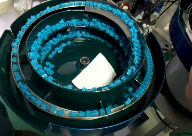
Figure 14: Close up view of part sorters which actually help align the components to the same orientation for the assembly machine.
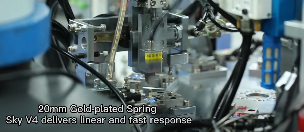
Figure 15: Springs being inserted into switch housings via an assembly process.
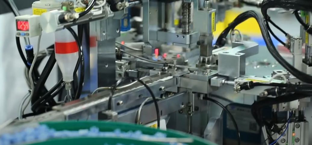
Figure 16: Top housings and stems being pressed onto switch bottom housings in similar fashion to the spring machine above.
In an extremely similar fashion to how the leaves are inserted into the bottom housings that are held tightly by machines, similar machines drop the springs into the switch and then compress the stem and top housing together with the bottom housings that have leaves and springs in them. Once the switch is fully put together, most assembly lines have machines which will tap the switches once or twice to make sure all of the components have been properly connected together. Some companies even have in-line force curve machines to quickly quality control their switches to make sure that they compress and release as they are expected to. While this may seem like a bit of overkill on the part of their quality control departments, here is what can happen to switches during this put together process…

Figure 17: Various different ways in which improperly aligned springs/housings can lead to defecting switches when combined.
Figure 18: Yet another switch whose spring was crushed during the assembly process.
All of this is if the switches even get springs at all, by the way! Sometimes switches can and do arrive from the factory completely from the factory with no springs at all. Or, in other very rare cases, this put together process can weed out thin, flimsy, and poorly casted parts.

Figure 19: Slider rails of a grey bottom housing mangled and broken during a misaligned assembly process.

Figure 20: Rare fully functional switches with housing assembly errors. LCET switch on the left having entire keycap mounting post sheared off and SP Star switch on the right having a top housing leg folded into the interior of the switch.
With this informative, albeit slightly unorthodox look behind the curtain that is switch manufacturing, I hope you’ve gained a newly found appreciation for just how lucky you are to likely have never encountered a defective switch before. If you want to see all of these processes with a lot more life and a lot less words, I’d highly recommend checking out the linked videos of switch production below. Interestingly, though, all of these videos and the pictures above don’t even begin to cover all of the possible ways that truly not-for-release switches can and do escape production facilities, either. I’m not even talking about my Cherry-red prototype top housings from Cherry, either – I’m talking about the most rare of defects: completely functional manufacturing accidents. Unfortunately, I only have a single example of this in my entire collection as I’ve only ever seen this occur once in my over half decade of active switch collecting now and it comes in the form of a completely tactile Kailh Burgundy switch. While normally linears, this error came in a batch of normally produced switches from Kailh with two of the stems seemingly accidentally being shot with burgundy-colored plastic in the Kailh Pro Purple tactile molds instead…

Figure 21: 1 of only 2 known instances of a tactile Burgundy stem being produced by Kailh.